Introducing RPI-SDR-TX Version 1.0.0
About rpi-sdr-tx
rpi‑sdr‑tx turns your Raspberry Pi into a fully functional SDR transmitter, handling RF from 5 kHz to 1.5 GHz without specialized RF hardware (though band‑pass filtering is recommended). In v1.0.0, we’ve significantly expanded features for hands-on experimentation and hardware flexibility.
Key Features in v1.0.0
- Complete USB gadget configuration: Use
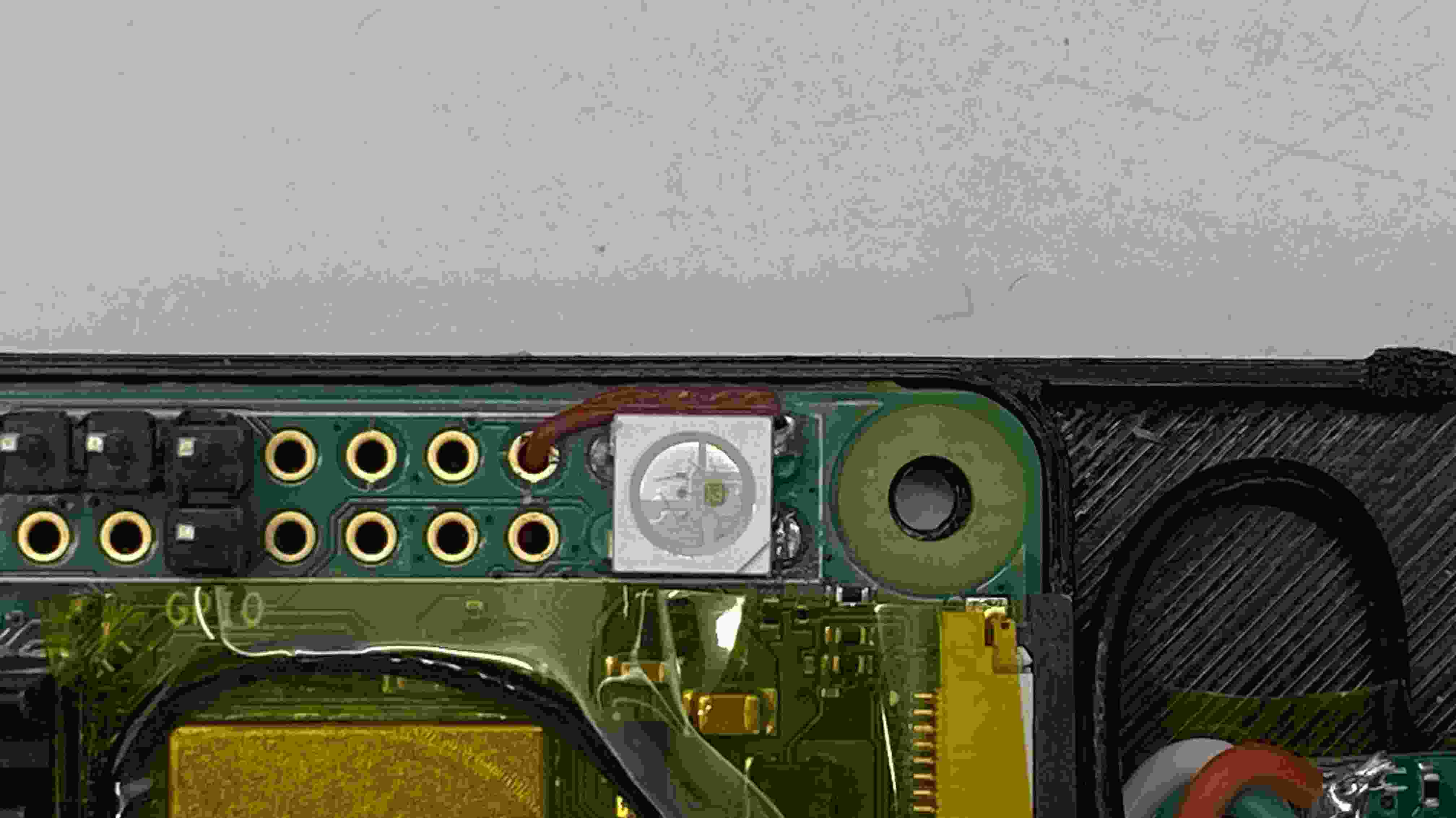
gttool to enable ACM (serial), RNDIS/Ethernet, HID, UAC (audio), and more — no extra host-side setup is needed. - WS2812B RGB LED support: Via SPI bit‑banging using
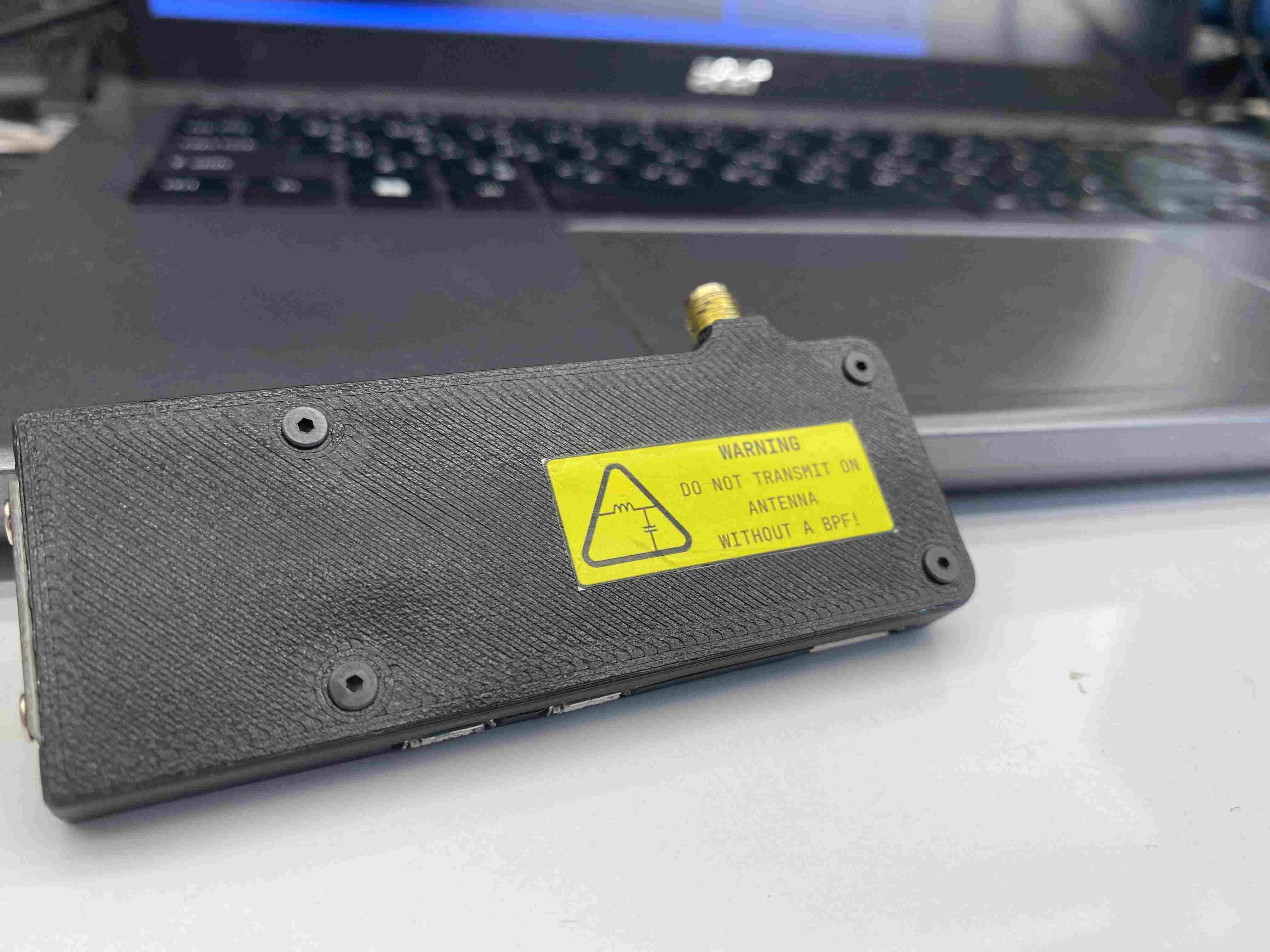
libbcm2835, empowering you to add visual feedback/control (e.g., status/status-driven patterns) to your SDR setup. - 3D‑printable case designs: Included for neat hardware packaging—stack your Pi, antenna, LEDs, and connectors cleanly and securely.
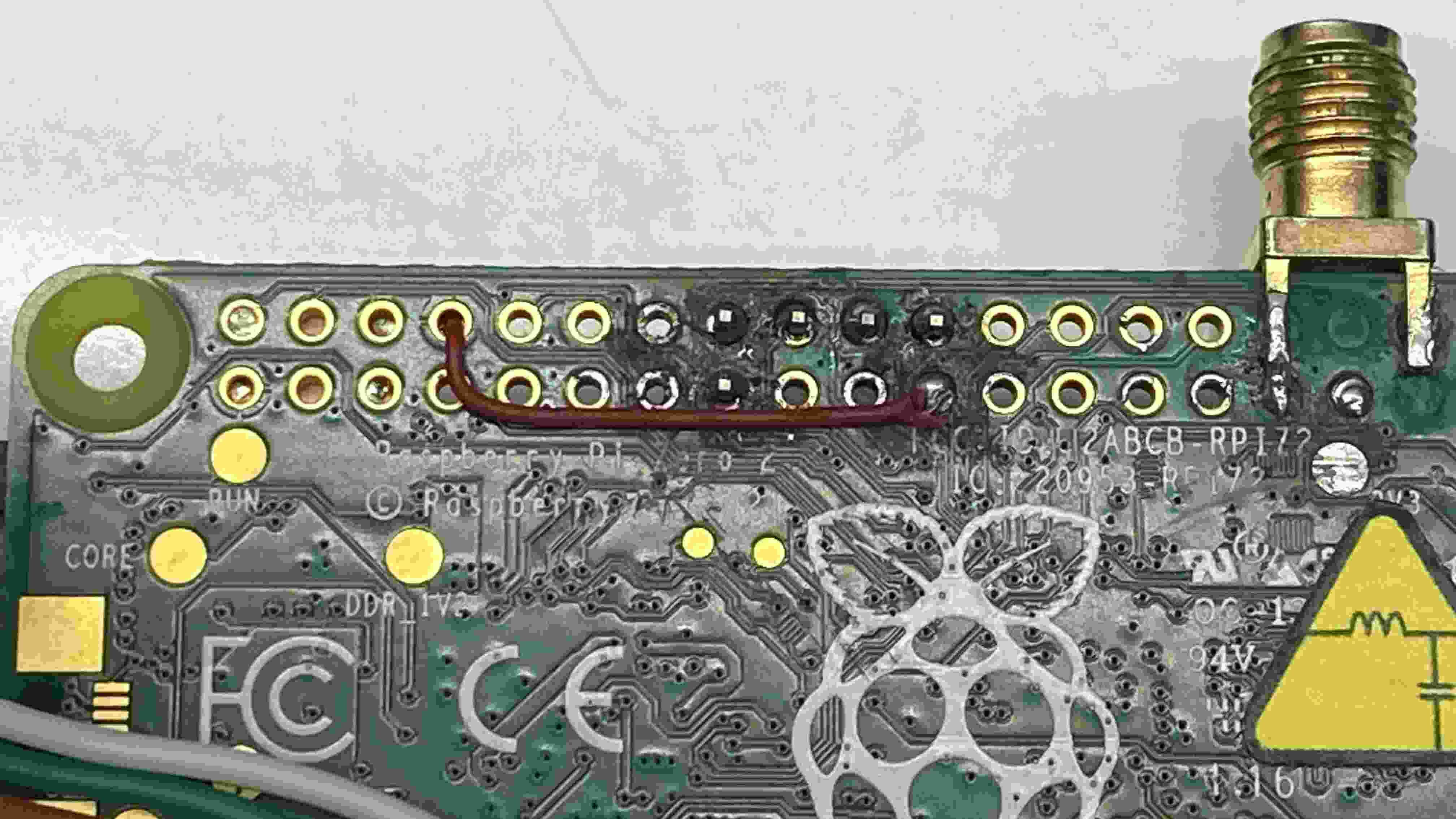
- Comprehensive hardware soldering tutorial, guiding users through safe wiring of GPIO, filter components, SMA antenna connections, and USB gadget header pins.
- Full compatibility with rpitx modes (AM/FM/SSB/Chirp/SSTV/etc.), an improved
easytest.shTUI, and enhanced usability for educational RF demos.
Warning
This remains an educational/experimental toolkit, not a certified radio transmitter. You must filter outputs to suppress harmonics and comply with local RF regulations—using unfiltered signals beyond tweaks can lead to interference or violations.
Why rpi‑sdr‑tx?
By building on F5OEO’s original rpitx project, this version—with its v1.0.0 release—packs a simplified install experience, pre‑configured demos, and improved usability tailored for hobbyists and learners. It makes high‑frequency RF experimentation accessible using just a Raspberry Pi.
How rpitx works
RPiTX uses the Raspberry Pi’s built-in PLL and clock peripheral to generate a carrier signal on a GPIO pin (typically GPIO 4 or 18). This square-wave signal (5 kHz–1500 MHz) acts as the RF carrier—harmonics are present, so filtering is essential.
1. Carrier Generation via PLL & Clock
- The Broadcom SoC’s phase-locked loop (PLL) is configured to a high frequency.
- A clock generator outputs a square wave on a GPIO pin.
- The fundamental of this clock becomes the RF carrier; harmonics are ignored with proper filtering.
2. Frequency (and Phase) Modulation
- RPiTX updates the PLL’s divisors in real time to shift the frequency, performing frequency modulation (FM).
- Phase modulation comes from party manipulating phase via frequency trajectory.
3. Amplitude Modulation via GPIO Drive Control
- Uses the peripheral’s drive-strength settings for amplitude adjustments. That provides ~8 amplitude levels (~3 bits), enabling ASK/OOK or amplitude shaping for SSB.
4. Generating Arbitrary I/Q Signals
- RPiTX can stream pre-generated I/Q samples (e.g. from GNU Radio or csdr).
- It applies those in real time using both frequency (PLL adjustments) and amplitude control, to broadcast SSB, SSTV, digital modes, and more.
5. Why It Works on Raspberry Pi
- Pi’s SoC exposes low-level control via mailbox and clock/DMA peripherals.
- This lets RPiTX run tight timing loops, rapidly reconfiguring clock output.
- Bit-banging any GPIO wouldn’t hit RF frequencies—hence the need for hardware clock support.
Warning
The output of the Raspberry Pi GPIO 4 (or 18) is a square wave, which contains harmonics. For example, if you transmit on 28 MHz, you will also transmit on:
- 28 x 3 = 84 MHz
- 28 x 5 = 140 MHz
- 28 x 7 = 196 MHz
- ...

and actually you may distrub some important radio communication services. Please don't do this! You can get into trouble! You have been warned.
In addition to the squre wave output, the spectrum is also affected by the PWM-based amplitude modulation implemented in rpitx.
- If you want to connect this to a real antenna, you should use a very good band-pass filter!
- Please check your signal output on a proper spectrum analyzer before ever using this on the air!
- In addition, only transmit if you have a proper license to do so.
How WS2812B over SPI Coexists with RPiTX’s GPCLK (GPIO4)
RPiTX uses GPCLK0 on GPIO 4 to generate RF continuously. Trying to bit‑bang WS2812 LEDs via PCM/PWM clashes and hangs the SoC. Using SPI0 MOSI (GPIO 10) avoids this conflict.
3‑bit SPI Encoding
- Protocol timing: WS2812 expects ~1.25 µs per bit (T0H ~0.4 µs, T1H ~0.85 µs).
- SPI works at ~2.5–4 MHz, so 3 SPI bits encode one WS2812 bit:
0→100(High‑Low‑Low)1→110(High‑High‑Low)
Timing Explanation
- At 3 MHz, each SPI bit is ~333 ns.
- Sending 3 bits = ~1.0 µs, aligning well with the needed ~1.25 µs WS2812 slot.
Data Flow
- Convert each color byte (G, R, B) into 24 WS bits.
- Encode each WS bit into 3 SPI bits:
100or110. - Send encoded data over SPI0 (GPIO 10) in one burst.
- Append a >50 µs low period (reset) by sending zeros or idling.
- WS2812 resets and latches the colors.
Benefits
- No interference with GPCLK0 on GPIO 4.
- SPI + DMA ensures consistent timing with minimal CPU load.
- Works well on BCM2835/2837/2711 SoCs.
Minimal Pseudocode ( C )
uint8_t encode3[2] = {0b100, 0b110};
void sendPixel(uint8_t G, uint8_t R, uint8_t B) {
  uint8_t buf[9];
  int idx=0, bit=7;
  for (uint8_t c : {G,R,B})
    for (int b=7; b>=0; b--) {
      uint8_t code = encode3[(c>>b)&1];
      for (int i=2; i>=0; i--) {
        buf[idx] |= ((code>>i)&1) << bit;
        if (--bit<0){ bit=7; idx++; }
      }
    }
  spi_write(buf,9);
  delay_us(80);  // latch reset
}
Downloads
Build Image download -> v1.0.0_rpi-sdr-tx_rpi02w_armhf.img.xz
Install script & Build script tutorial -> Release RPI-SDR-TX Version 1.0.0