PCB & FPC

This page documents the core PCB and FPC architecture of the Lichee-Jack hardware platform. The design is fully open-source, modular, and intended for reproducible manufacturing and hardware research.
All PCB-related source files are maintained in:
Hardware System Overview
The complete Lichee-Jack hardware stack consists of three primary boards, designed to work together as a compact and extensible system around the LicheeRV Nano.
LicheeRV Nano
│
├── EXT_BOARD_FPC ──┐
│ ├── HEADER_BOARD ── External Modules
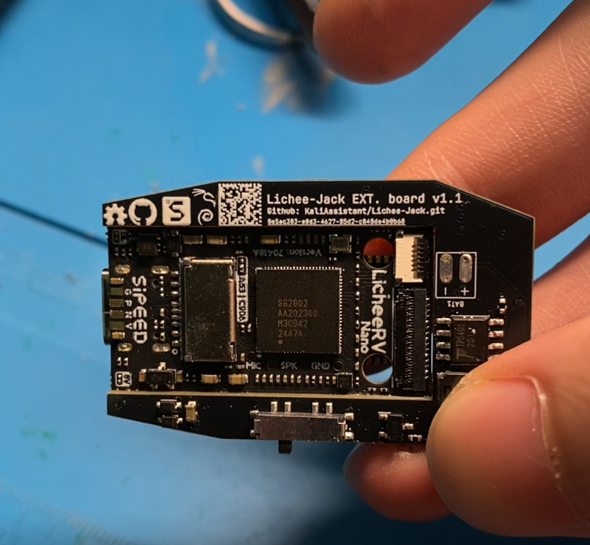
└── EXT_BOARD ──────┘1. Lichee-Jack_EXT_BOARD
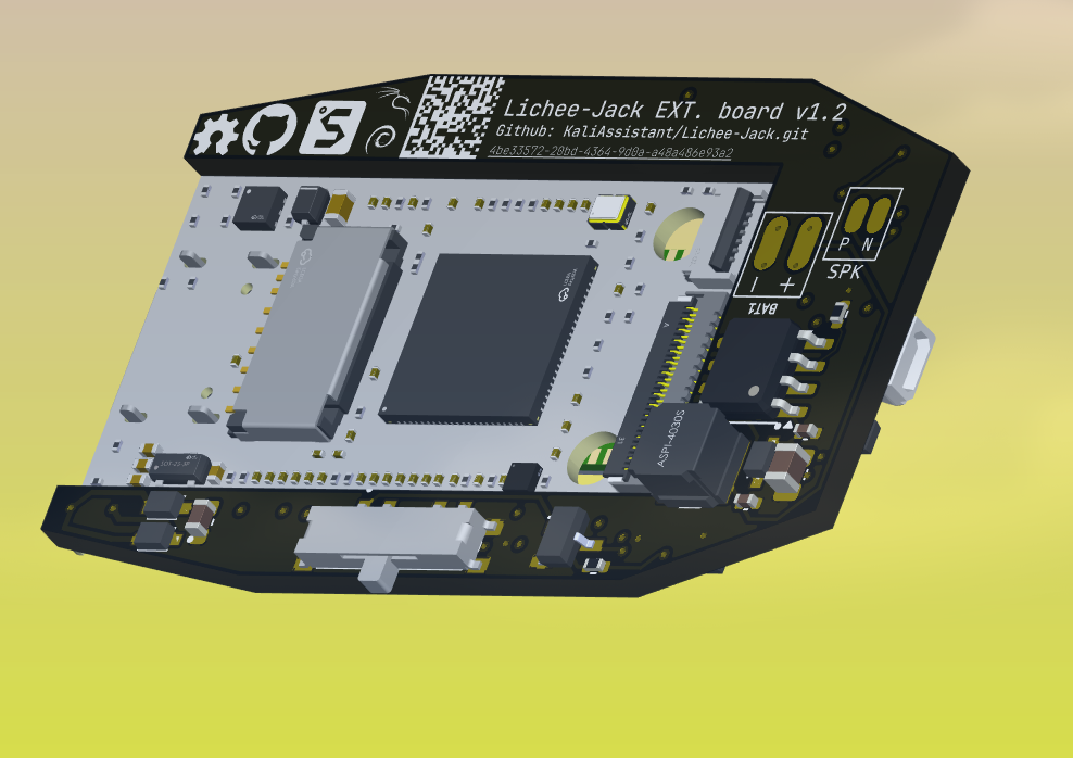
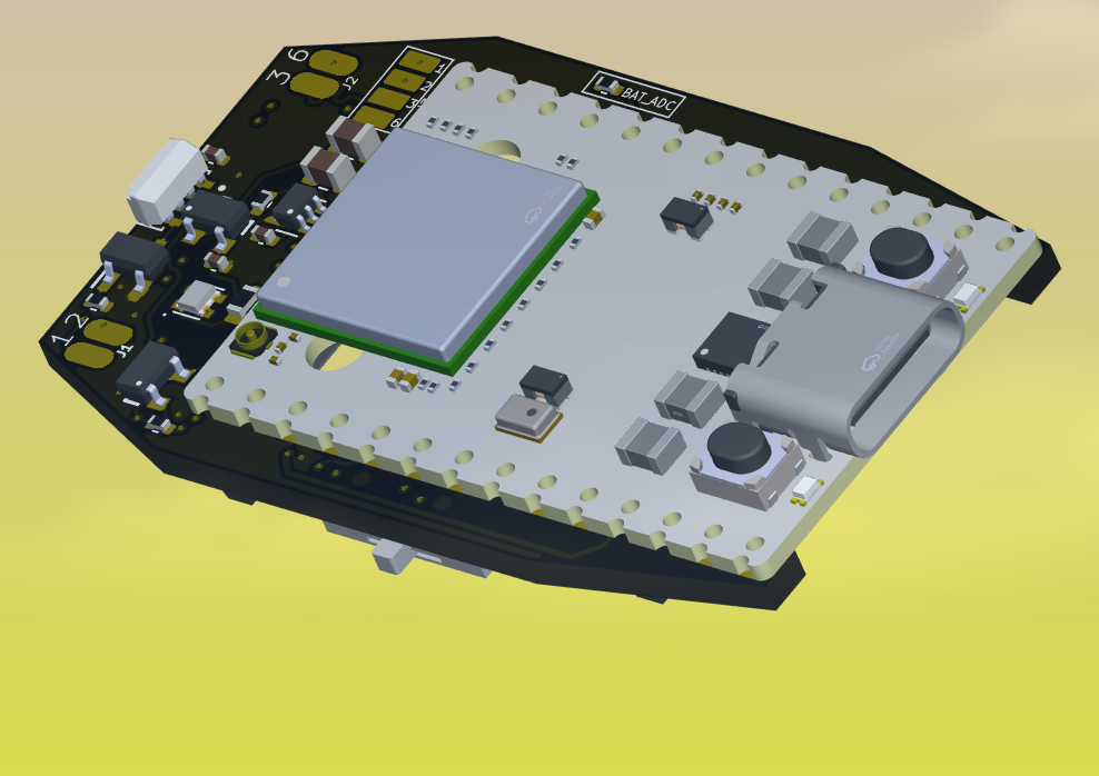
The EXT_BOARD is the main functional extension PCB. It provides power management, peripherals, and system control.
Key features:
- Battery management system (Li-Po)
- WS2812 RGB status LED
- SP3T hardware control switch
- Ethernet signal breakout pads
- Peripheral support circuitry
Mechanical specifications:
- PCB thickness: 1.6 mm
- Standard FR-4
This board is the only PCB suitable for full PCBA assembly by manufacturers.
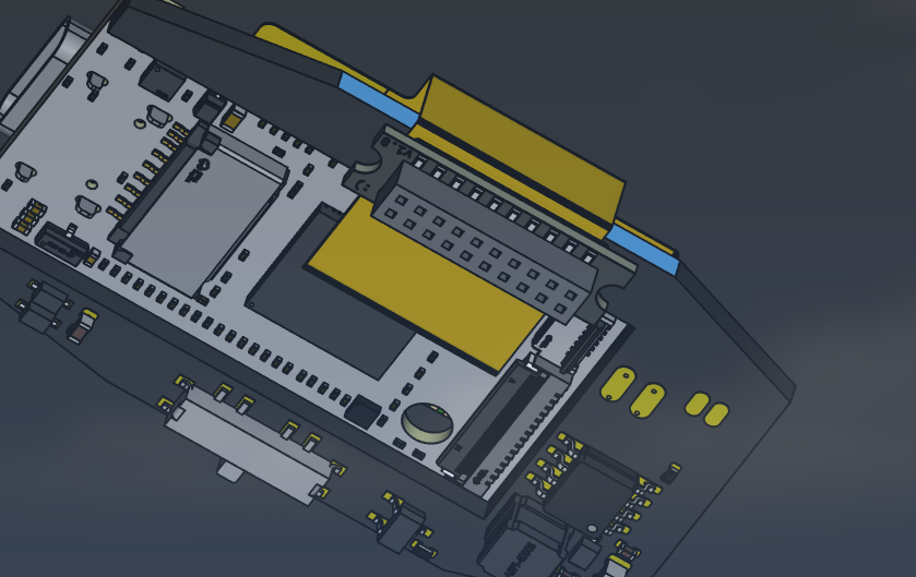
2. Lichee-Jack_EXT_BOARD_FPC
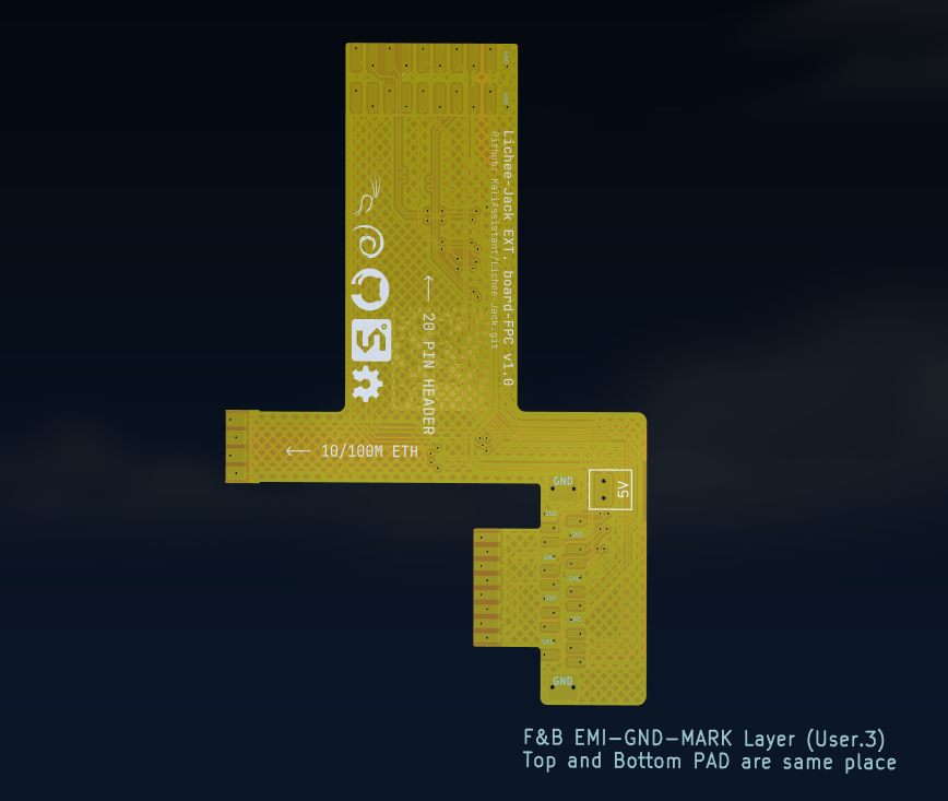
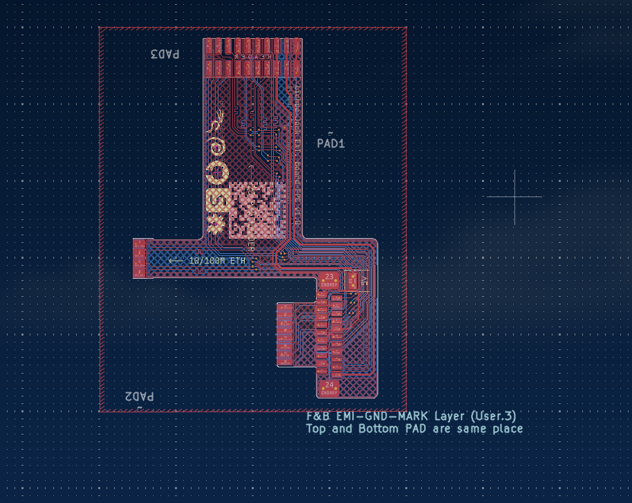
The EXT_BOARD_FPC is a flexible interconnect used to bridge signals between the LicheeRV Nano, EXT_BOARD, and HEADER_BOARD.
Responsibilities:
- ETH pads: LicheeRV Nano → EXT_BOARD
- CSI pads: LicheeRV Nano → HEADER_BOARD
- Additional GPIO and expansion signals
Notes:
- Designed for manual soldering
- Enables compact stacking and enclosure compatibility
3. Lichee-Jack_HEADER_BOARD
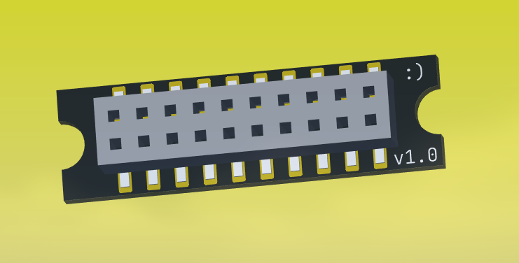
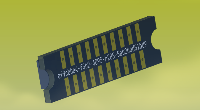
The HEADER_BOARD acts as an adapter and signal breakout layer for external extension modules.
Functions:
- Converts FPC signals to a 1.27 mm 2×10 SMT header
- Provides mechanical stability for stacked modules
- Interface for custom extension boards
Mechanical specifications:
- PCB thickness: 0.8 mm
Assembly Notes
Always follow the recommended soldering temperatures to prevent PCB or component damage.
EXT_BOARD
-
Use high-temperature solder paste
- Sn63/Pb37 or SAC305
EXT_BOARD_FPC
- Hand-solder using a standard soldering iron
HEADER_BOARD
- Use high-temperature solder paste
LicheeRV Nano + EXT_BOARD
-
Use low-temperature solder paste
- Sn42/Bi58 (recommended)
Battery Specification
- Type: Li-Po 3.7 V
- Capacity: 200 mAh
- Model: 402030
This battery size is verified to fit the official 3D-printed enclosure.
5V Power Safety Notes
The LicheeRV Nano connects VBUS ↔ VSYS via a factory-installed 0Ω resistor (marked 5V).
When supplying external 5V power, you must remove this 0Ω resistor to avoid back-powering and damage.
Enclosure Compatibility Assembly Guide
To assemble the system so it fits inside the 3D-printed case:
Step 1. Remove CSI Connector
- Desolder the CSI camera connector from the LicheeRV Nano
Step 2. Install HEADER_BOARD
- Populate SMT connectors according to the BOM
Step 3. Connect EXT_BOARD_FPC
-
Solder the FPC between:
- LicheeRV Nano
- HEADER_BOARD
- EXT_BOARD
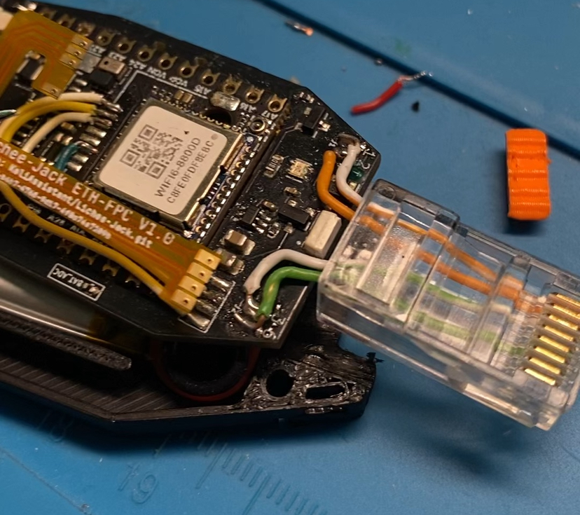
Step 4. Ethernet Wiring
-
Use a short 4P or 8P Ethernet cable
-
Solder to EXT_BOARD ETH pads:
- WOG, OG, WG, G → RJ45 pins 1, 2, 3, 6
-
Crimp an 8P8C connector on the cable end
PCB Manufacturing & PCBA
You may submit the EXT_BOARD for assembly using:
- Gerber files
- BOM
- CPL
Supported manufacturers include:
- JLCPCB
- PCBWay
- Seeed Studio
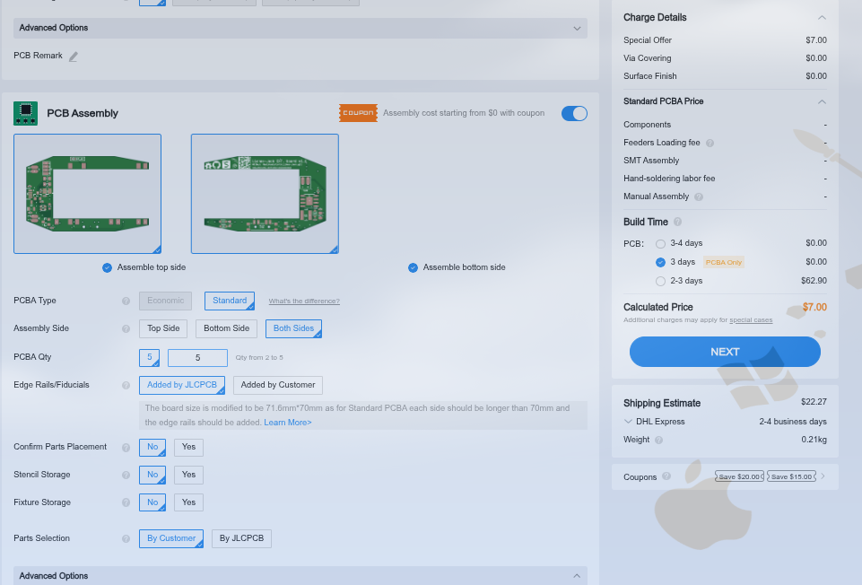
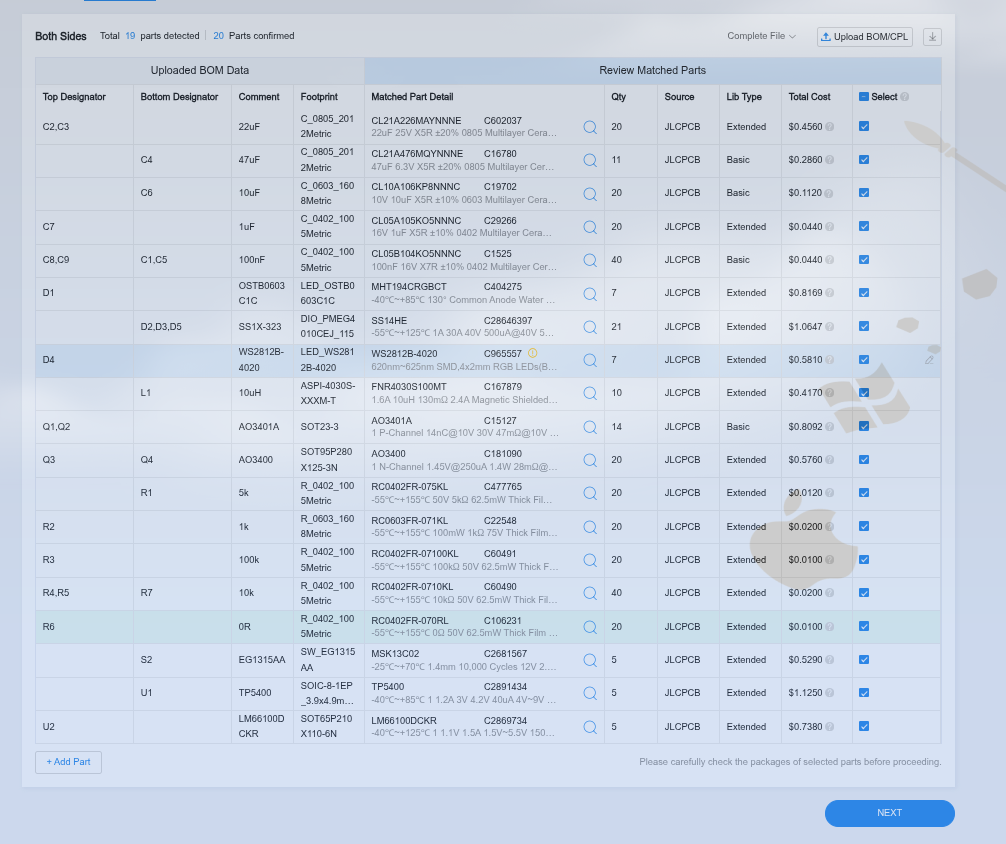
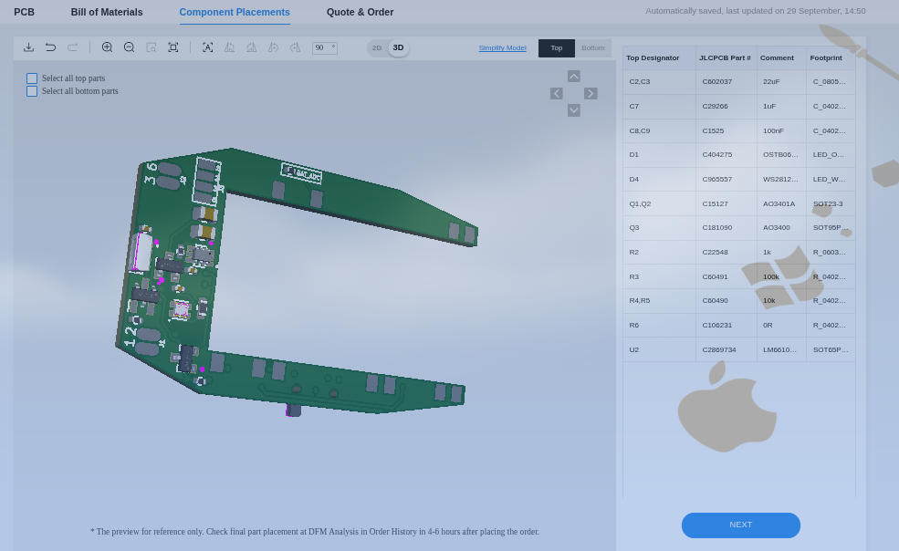
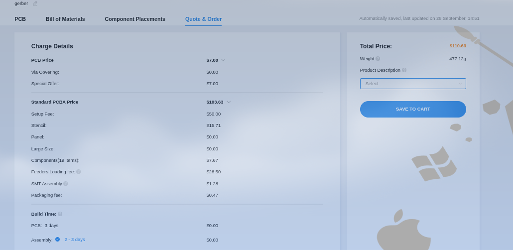
Only the EXT_BOARD can be assembled automatically. The LicheeRV Nano and FPC connections require manual work unless custom services are arranged. the manufacturer will only assemble the extension board (EXT_BOARD). The SIPEED LicheeRV Nano module itself is not included in the PCBA service — you must solder the LicheeRV Nano to the EXT_BOARD yourself after receiving the assembled PCBs, unless you explicitly arrange a custom assembly that includes the Nano (rare and often expensive).
If you want a fully populated, plug-and-play unit, contact the PCBA vendor beforehand and confirm which parts they will source and assemble (and whether they can handle the LicheeRV Nano module). Otherwise expect to receive the EXT_BOARD fully assembled and still needing the LicheeRV Nano and a few user-installed parts.
PCB Version History
Always use the latest revision for new builds.
v1.0 → v1.1
-
Added missing Schottky diode (PWR_IN → PWR_OUT)
-
Fixed boot issue:
- SP3T pos1 rerouted from GPIO-A16 → GPIO-A15
v1.1 → v1.0.32 (EXT_BOARD)
-
Fixed UART0-RX conflict (GPIO-A17)
-
Rerouted SP3T pos2 → GPIO-A24
-
Added speaker pads
-
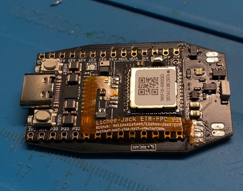
Replaced legacy ETH-FPC design with:
- Stack board
- HEADER_BOARD
- New EXT_BOARD_FPC