20-pin GPIO
Lichee-Jack replaces the original LicheeRV-Nano CSI FFC connector with a 1.27 mm dual-row 2×10 SMT header, providing a compact and flexible GPIO expansion interface for external modules.
This design turns the CSI pad area into a general-purpose extension port while maintaining good signal integrity and mechanical reliability.
Header FPC & Header Board (Legacy Design)
In early hardware revisions, the GPIO expansion was implemented using a Header-FPC + Header-Board architecture:
-
A custom FPC was designed to solder directly onto the CSI pads of the LicheeRV-Nano
-
The FPC connects to a small header board
-
The header board is 0.8 mm thick, with:
- Top side: 1.27 mm 2×10 SMT header
- Bottom side: FPC solder pads
This approach enabled early prototyping and validation of the 20-pin GPIO concept, but introduced additional connectors and assembly steps.
Extension Board FPC (Latest Design)
In the latest hardware revision, the original ETH-FPC and Header-FPC were consolidated into a single Extension Board FPC.
This new architecture:
- Replaces multiple FPC cables with one unified FPC
- Carries GPIO, Ethernet, and extension signals together
- Directly interfaces with the Extension Board
Benefits
- Simplified inter-board connections
- Reduced connector count
- Improved mechanical stability
- Better manufacturability and assembly reliability
This change significantly improves robustness while reducing BOM complexity.
Pinout
The following diagram shows the 20-pin GPIO header pinout as exposed on the Lichee-Jack Extension Board.
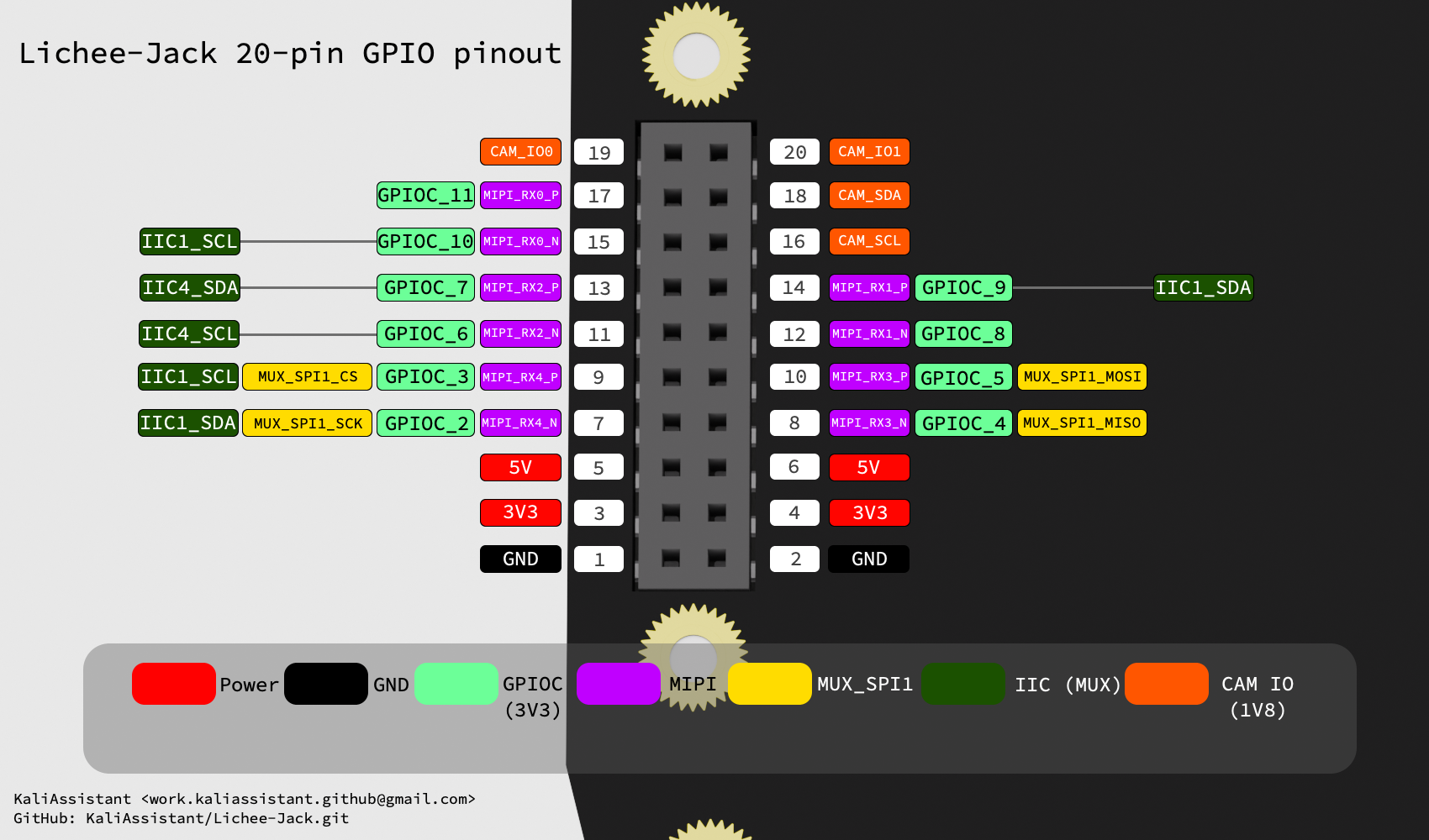
Signal availability and multiplexing depend on SoC pinmux configuration. Refer to the software documentation for GPIO / SPI / I2C usage details.
Related Documentation
For detailed PCB revisions and mechanical changes, refer to:
For Ethernet-related design details, see: